
Yakovlev Yak-55M RC Plane plans
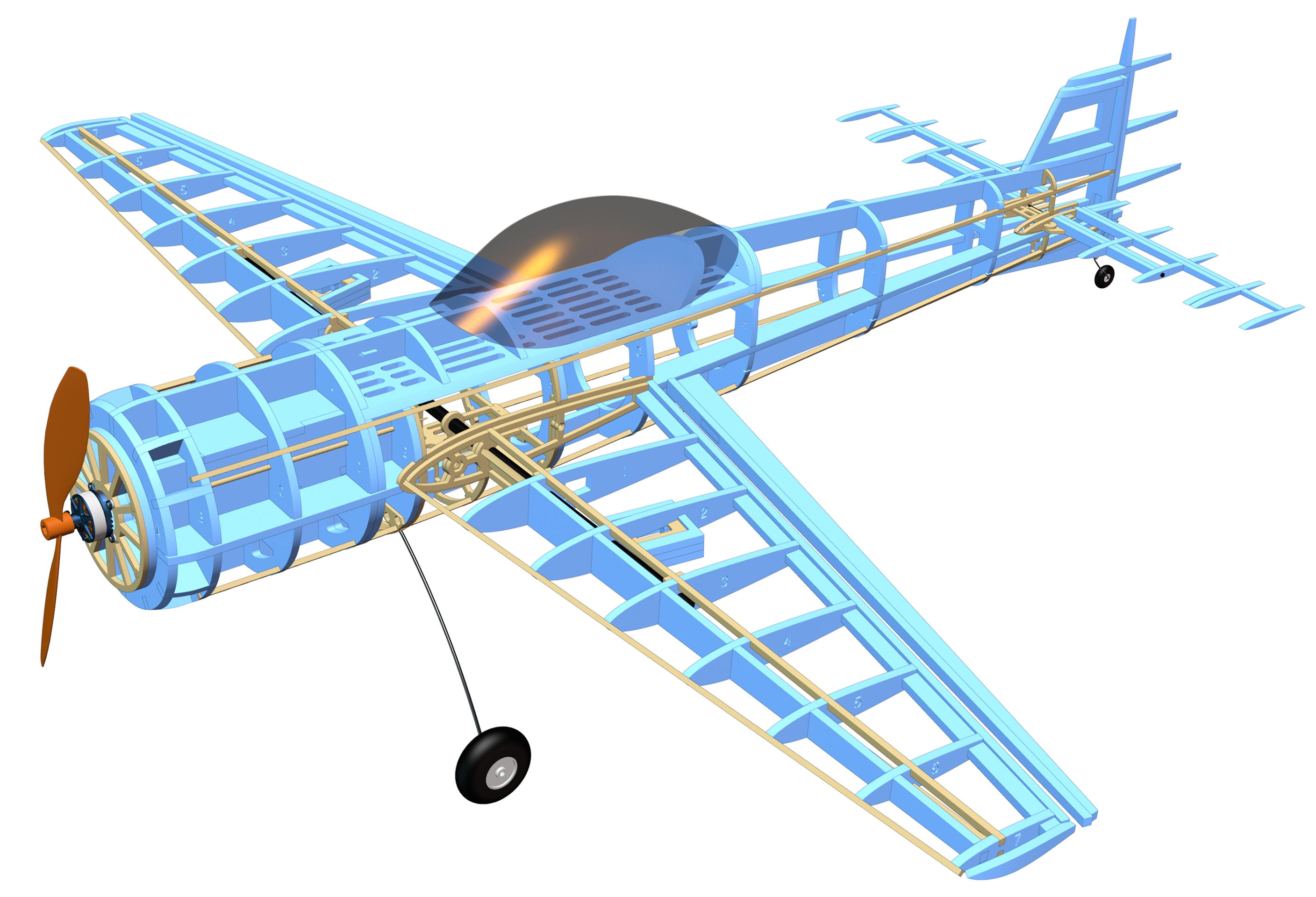
Wingspan: 1000 mm (39,4")
Length (w/o motor): 924 mm
Flying Weight: 462 g
Motor: SunnySky X2305 KV1450  (25g), Amazon
Propeller: GWS EP 1047 (Slow Fly)
ESC: SunnySky X 18A (9g),Amazon
Servos: EMAX ES08D II (9g)x4
LiPo battery: 1500mah 2S (85 g)
Stainless Steel Spring Wire 2 mm
Wheels 50mm (2")
Carbon wing tube: 8x7x500mm
Horizontal stabilizer carbon tube 500x3x2mm
Carbon push rods: 500x2x1mm
Nylon Control Horn with Clevis (0,52+0,34g):
Control Horn (0,5g)
Hinge Linker (24x12mm):
Thumb Screw Bolts (M4x12)
Nylon nuts: M3, M4
Nylon screws: M2
Materials: 5mm XPS foam (in the picture it's blue). 3x3mm Balsa Wood Sticks (fuselage and leading edge of the wing) 4x4mm - wing spars; 3mm XPS foam - wing, rudder and elevator skin; 3x200mm Bamboo Skewers; Neodymium magnets 3x5mm ; Nylon screws: M2x6mm (for servos), M2.5x4mm (for horizontal stabilizer), M3x10mm Phillips Flat Head Bolts; transparent 0.3mm PET-A (PET-G) plastic sheet for canopy
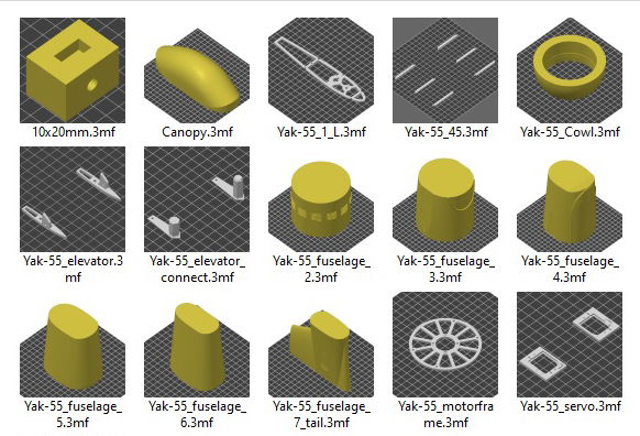
Plans (DXF for laser cutting, 3MF for 3D printing)
Download STL, 3MF and DXF files (€7) в pубляx
The white XPS foam was cut using a xTool P2 CO2 Laser Cutter (diode laser doesn't cut white and blue foam !)
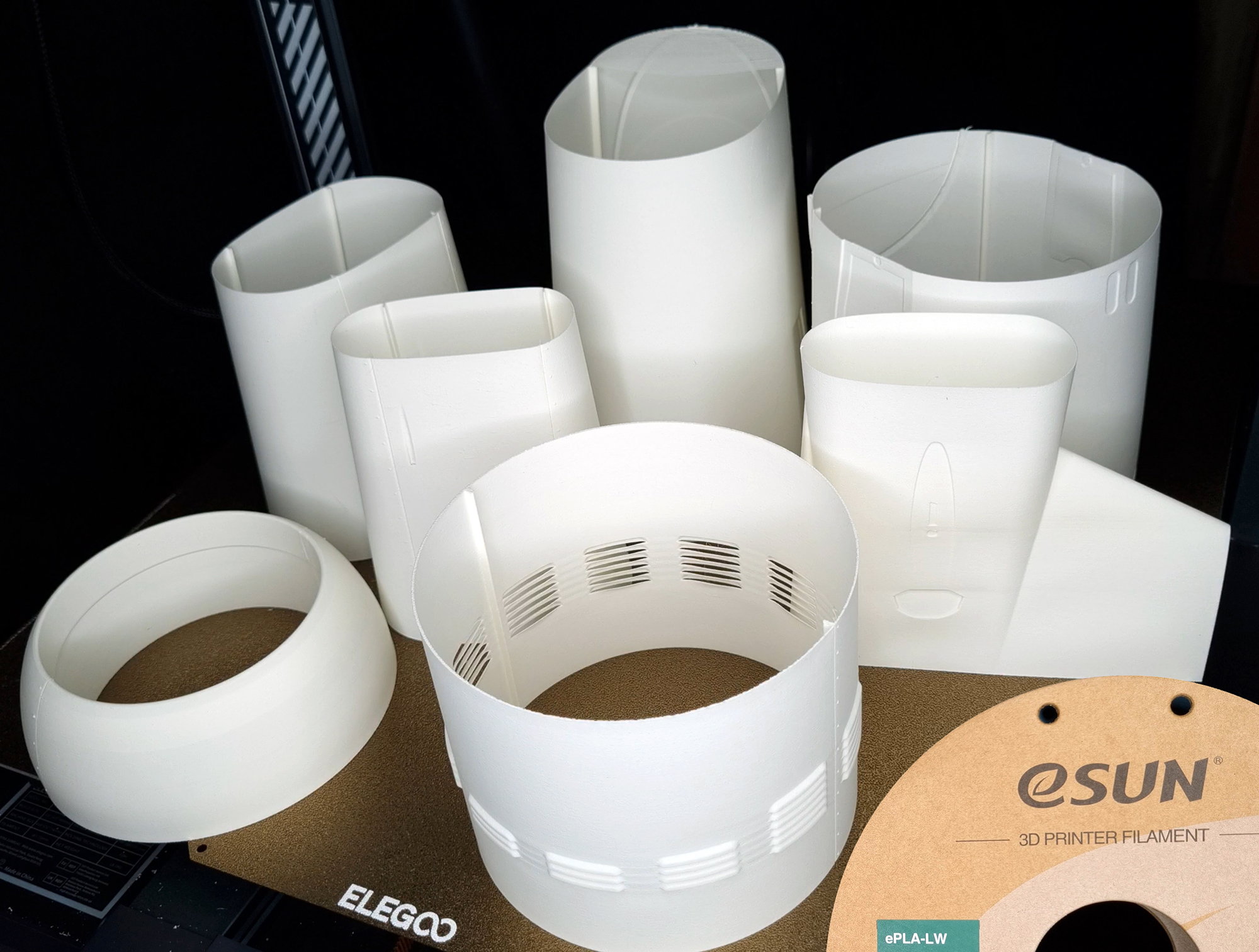
3D printed fuselage skin
All settings in .3mf files (Prusa Slicer)
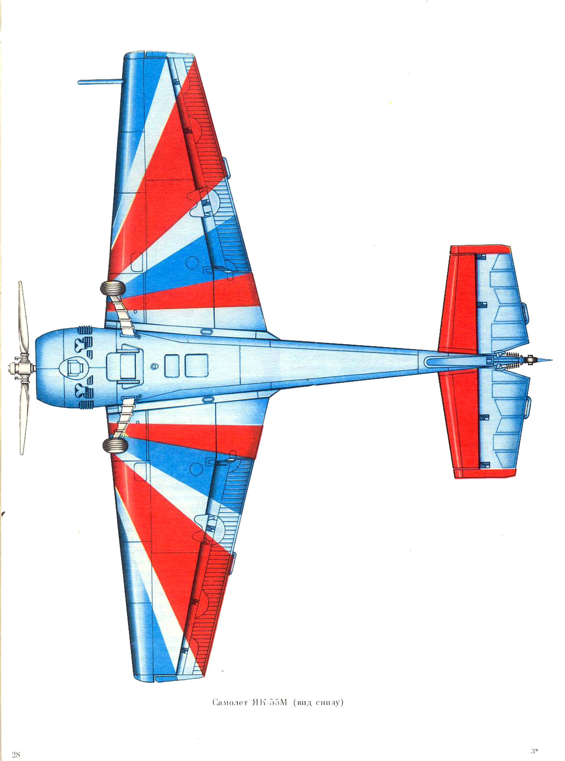
The Yak-55 is a single-seat aerobatic aircraft designed to train pilots and to participate in aerobatic competitions.
The aircraft is capable of performing simple, complex and aerobatic maneuvers. At the same time, performing reverse aerobatics is practically no different from direct aerobatics. High power-to-weight ratio combined with good controllability allows performing aerobatic maneuvers without losing altitude.
According to the aerodynamic design, the aircraft is a monoplane with a mid-mounted free-bearing symmetrical wing, non-retractable tricycle landing gear with a tail support. The aircraft is equipped with a piston radial single-row nine-cylinder M-14P air-cooled engine with a capacity of 360 hp (265 kW) with a V-530TA-D35 variable-pitch propeller. The aircraft is equipped with a VHF radio station for communication with ground stations and other aircraft. The flight and navigation equipment ensures daytime piloting of the aircraft in simple weather conditions.
The airframe consists of a fuselage, wing and tail unit.
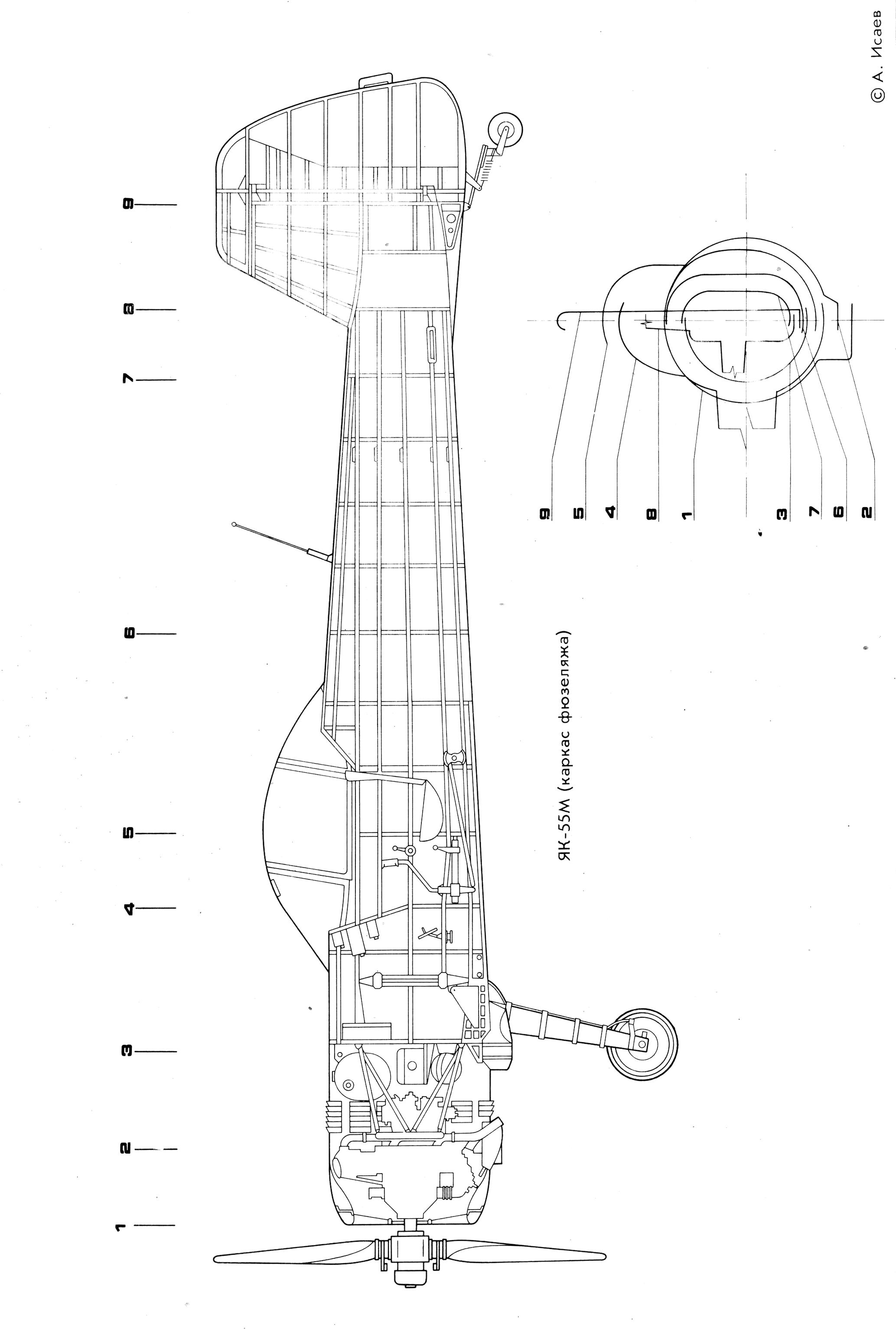
The fuselage is an all-metal semi-monocoque. The main material for the frame and fuselage skin elements is aluminum alloy D16, used in the form of sections and sheets. The fuselage frame is formed by a transverse set consisting of 15 main frames and one additional (No. 6A), and a longitudinal set including 14 stringers and four spars.

The pilot's cabin is located on the section of frames No. 2 and 8. The cutout for the cabin is edged with upper spars to maintain rigidity. The support beams of the chassis springs are attached to frame No. 2 in the lower part, and the spring attachment unit is installed on the lower chord of the fuselage beam. Two rear wing attachment units are located on frame No. 5. The front fin and stabilizer spars are permanently fastened to the reinforced frame No. 13 with bolts and rivets. The tail landing gear brackets are attached to the lower sections of frames No. 14 and 15.

The cockpit floor is located at the level of stringer No. 6 between frames No. 2–6 of the fuselage. There are cutouts in the floor for installing pedals, the aircraft control stick, and for the aileron control rocker. The fuselage skin is made of sheet duralumin.
There are hatches in the fuselage skin for access to the aircraft system units. The cutouts for them are edged with overlays and covered with covers. On the left side, behind frame No. 12, a metallization unit is riveted to the skin, which is a contact socket into which the plug of the device for grounding the aircraft when parked is inserted.

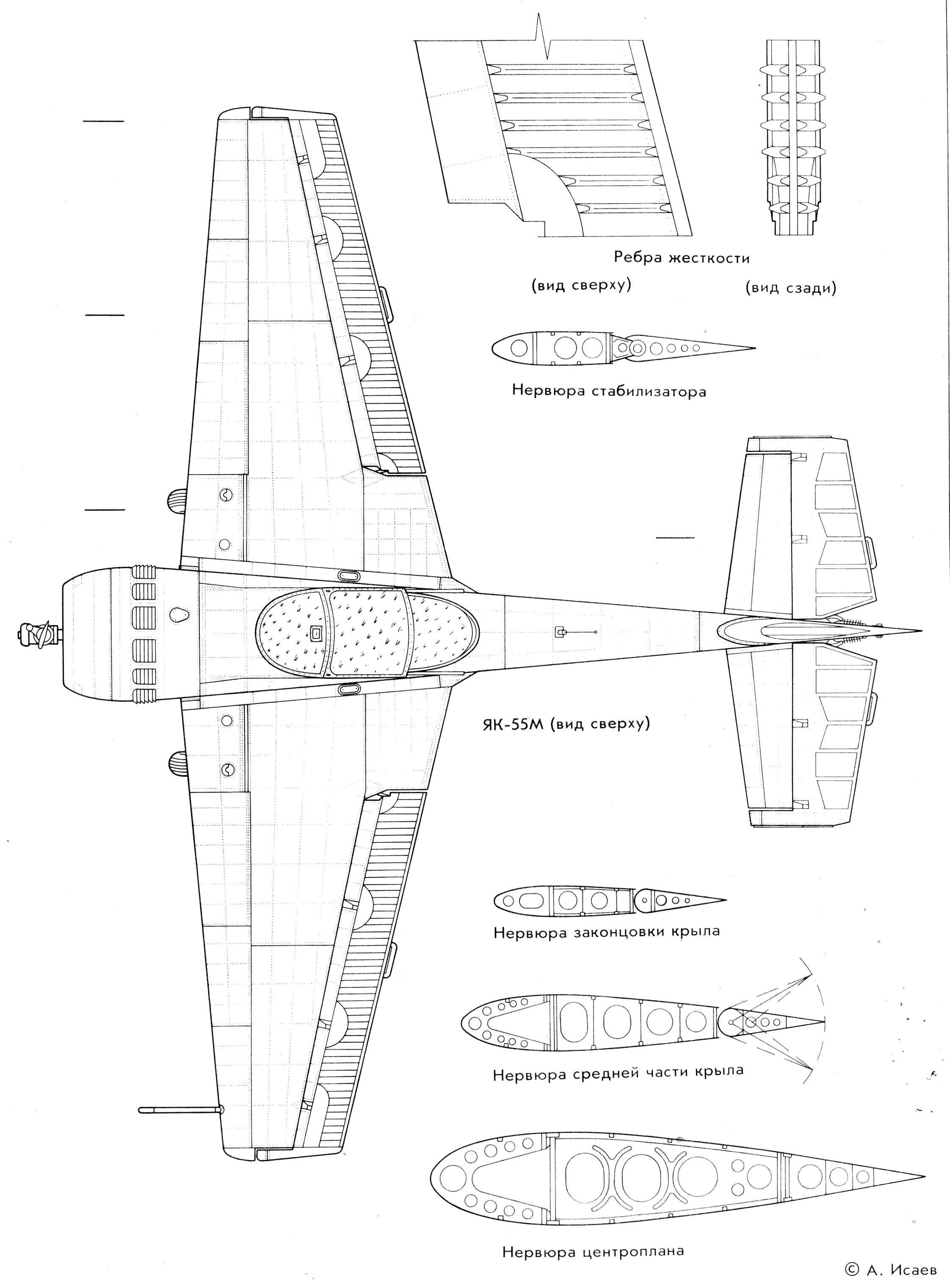
The wing is made according to a single-spar scheme with a working skin and consists of two detachable parts, each of which is equipped with an aileron. The wing console is joined to the fuselage using two units located on the spar, and a third unit located on the rear wall of the console. The mating docking units on the fuselage are installed on the power beam of frames No. 2 and 5. The joints of the consoles with the fuselage are closed with tension bands. In the nose of the wing, limited by the skin, spar and walls of ribs No. 1 and 4, the fuel compartments are located.
The wing frame is formed by a longitudinal and transverse set. The longitudinal set consists of a spar, a rear wall, which is also the aileron slot lining, and a set of stringers. The transverse set of the wing consists of 13 ribs and nine noses. The rib walls have relief holes. A bracket for attaching the air pressure receiver is installed on the nose of rib No. 12 of the left console.
The wing skin is made of D16-ATV duralumin sheets of various thicknesses. In the lower part of the console skin, there are service hatches for access to the control system rockers, aileron suspension units and for access to the fuel compartment wall. The wing tips are made of fiberglass with internal stiffeners.
The fuel compartment is located between ribs No. 1 and 4. The compartment is assembled on an internal sealant, covered with a fuel-resistant material and subjected to surface sealing. The capacity of each of the two fuel tanks is 95 liters.
The wing aileron consists of a spar, nose skin, upper and lower tail skins, two end ribs, 20 noses and four suspension brackets, four diaphragms, a trailing edge, a fixed trim tab, a balancing weight, and remote and “horn” compensators.
The tail unit of the aircraft has a trapezoidal shape and consists of horizontal and vertical tail units. The vertical stabilizer and vertical stabilizer are permanently attached to the fuselage with bolts and rivets. The contours of the joint between the vertical stabilizer and the fuselage are edged with side angles riveted to the vertical stabilizer and the fuselage. The horizontal and vertical stabilizer section profiles are symmetrical.
The stabilizer is formed by longitudinal and transverse sets and skin. The longitudinal set consists of two spars and four stringers, the transverse set consists of ten ribs. The elevator suspension brackets are bolted and rivet to ribs No. 1, 3 and 5 and to the wall of the rear spar. Metal-fluoroplastic bushings are pressed into the bracket holes for the elevator suspension axes.
The elevator, made of two halves, has "horn" aerodynamic compensators, weight balancers, suspension units on ribs No. 4 and 7, uncontrolled trimmers (plates) and a control sector. The frame of each half of the elevator consists of one spar, eight ribs, six noses, five diaphragms and a rear rib. In the nose of the "horn" compensator, a weight balancer consisting of a load and a correction plate is bolted to the diaphragm. The elevator is covered with AM-100 fabric. There are drainage holes in the lower fabric covering of the rudder near the rear rib.
The keel has a trapezoidal shape and is formed by transverse and longitudinal sets. The longitudinal set consists of two spars and four stringers. The transverse set of the keel frame is formed by three ribs. The keel is permanently attached to the fuselage, the keel skin is made of D16-ATV duralumin sheets.
The single-spar rudder has a horn aerodynamic compensation, weight balancing, an uncontrolled trimmer (plate), a control sector and hinge brackets. The rudder frame consists of a spar, eight ribs, five noses, two diaphragms, five boxes, eight stringers and a rim. The frontal skin and the wingtip skin are working and are made of D16-A-L duralumin. The entire rudder is covered with AM-100 fabric. There are three drainage holes in the lower section of the rear rim.
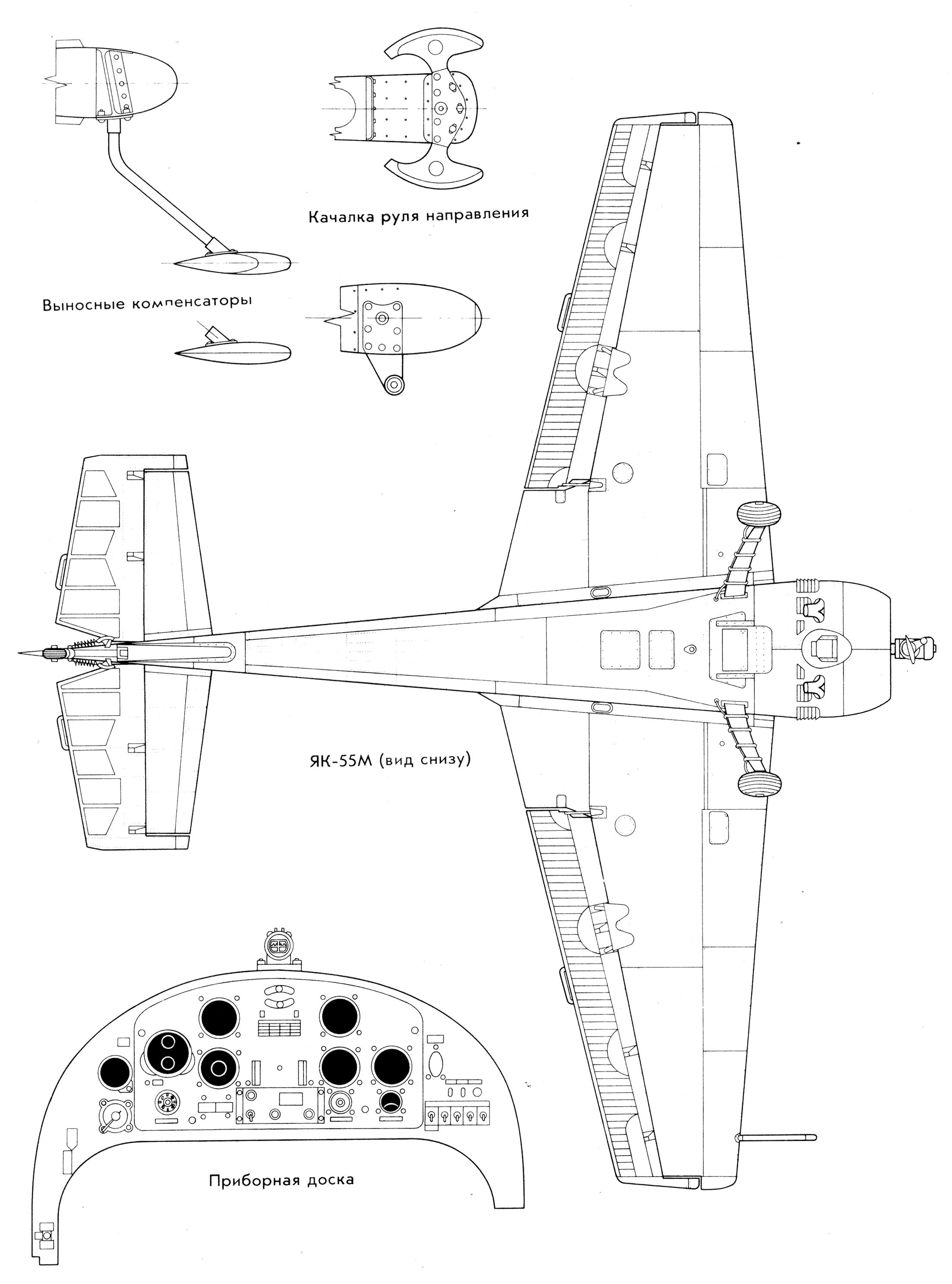
The pilot's cabin is unpressurized, with outside air ventilation, located in the front part of the fuselage and is limited in front and behind by frames No. 2 and 6, respectively, at the bottom - by the floor, and at the top - by the canopy. The geometric dimensions of the cabin, the design of its canopy, the seat with a harness, the presence of a parachute, the system of adjusting the pedals to the height of the pilot, the layout of the instrument panel and control panels provide the pilot with a comfortable position for piloting, monitoring instrument readings, good reach of the control areas, the necessary view of the outside space at all stages of flight and when taxiing on the ground, reliable fixation in the seat and the ability to emergency abandon the aircraft.
The interior trim of the cabin consists of side panels, two front partitions located behind the back of the seat, and one lower panel, which is attached to the fixed seat pan. The side panels and rear partitions are made of D16AM-lO.5 material, covered on the front side with PDOAZ-25 light-gray film. But the edges of the film are folded and glued to the paneling. The lower paneling is made of D16AM-lO.5 material and painted with AC-1115 enamel to match the film. All panels are fastened along the contour with screws and self-locking nuts to profiles riveted to the fuselage frame and seat pan.
The canopy has a streamlined teardrop shape and provides sufficient visibility when piloting and moving the aircraft on the ground. The canopy consists of a fixed visor and rear part and a sliding middle part.
The aircraft is equipped with ventilation of the cabin with a counter-current air flow. For this purpose, a ventilation device is installed in the upper part of the canopy glazing, which consists of an air intake, a screen, a flange and a spring with a lock. The amount of air entering the cabin is adjusted manually by the pilot. In this case, the ventilation device intake is fixed in three positions - open, half-open and closed. In the closed position, the intake is flush with the surface of the canopy glazing.
The pilot's seat is non-adjustable and is installed in the cabin between frames No. 4 and 6. It consists of a cup, a removable backrest, a soft cushion and is equipped with a pilot's harness. The seat cup is made of duralumin sheet, the backrest is assembled from a rigid frame and a soft cushion. The harness fixes the pilot in the seat and consists of five belts (two shoulder, two waist and middle) and a central lock. The belts are made of woven tapes and are equipped with shackles and adjusting buckles. To improve the pilot's comfort, the waist belts are equipped with a corset, and the shoulder belts with soft pads.
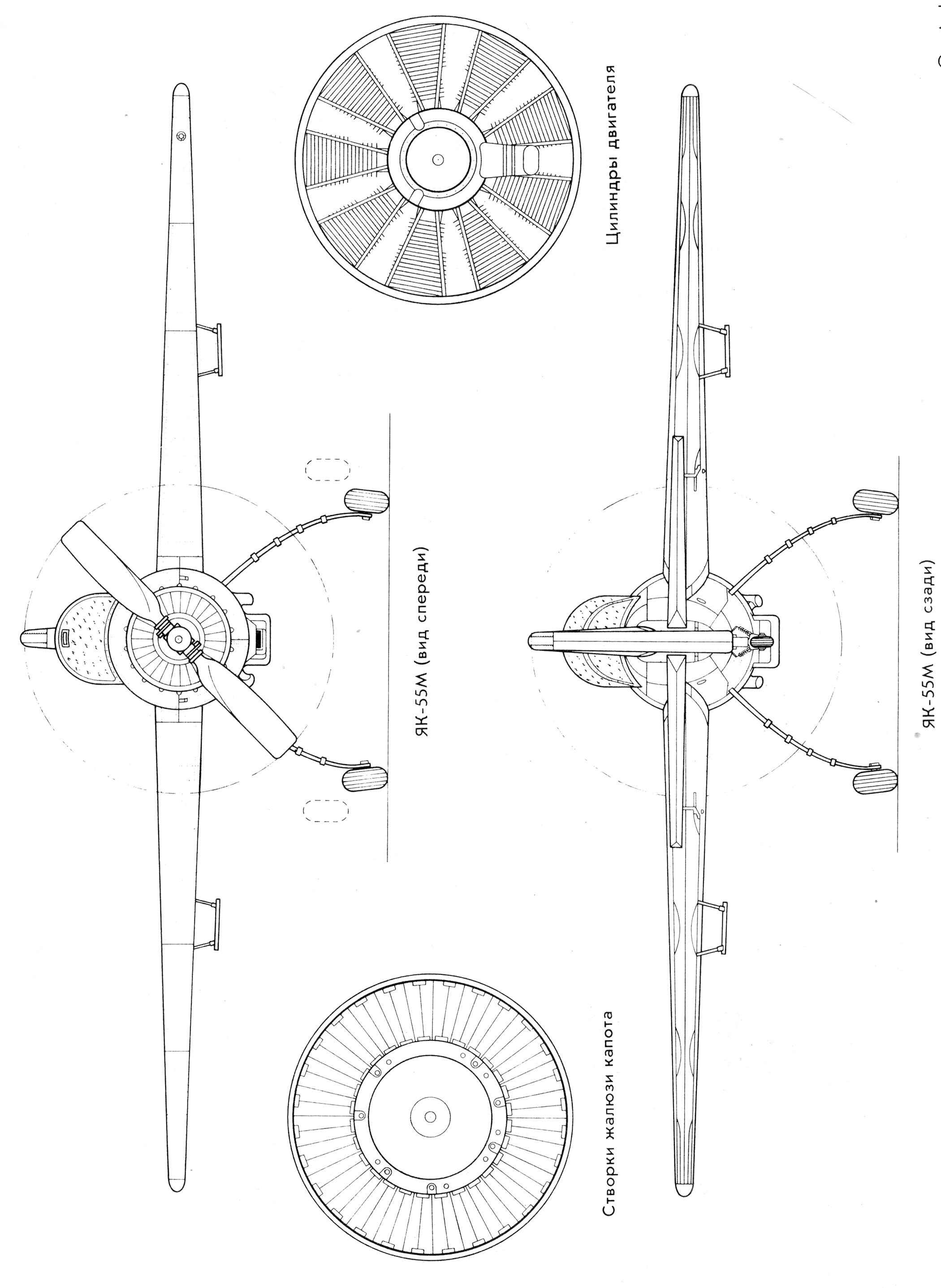
The aircraft landing gear is non-retractable, tricycle, with a tail support. All three spring-type supports are attached to the fuselage frame. The main supports are attached to a bracket mounted on the cross beam of frame No. 2, and rest on the longitudinal beams located on the left and right in the lower part of the fuselage between frames No. 1 and 2. One KT-214 brake wheel with a 400x150 mm tire is installed on the main supports. The tail support is attached along frame No. 14 to brackets secured from the outside in the lower part of the fuselage between frames No. 12 and 15, and rests on bushings installed with bolts on the same brackets. The tail support with a steerable wheel is installed on the spring. The fork on the support is connected to the rudder via springs. The main characteristics of the chassis are given below.
Track (aircraft on lifts) 2.00 m
Track (aircraft with parking compression of springs) 2.40 m
Base 5.71 m
Aircraft parking angle 9°40'
Wheel camber 14°±30'
Distance from the end of the propeller blades to the ground with the aircraft in the flight line 370 mm
The wheel braking system is hydraulic with differential braking of the right and left wheels. It consists of two hydraulic cylinders, intermediate rockers, brackets and oil pipelines.
Aircraft control system
The aircraft is controlled from the cockpit using the stick and pedals. Rigid tubular rods and cables are used in the control lines. All articulated joints of the aircraft control system parts are metallized.
The elevator is controlled by longitudinal movements of the control stick. When the control stick is fully deflected "towards you" or "away from you", the elevator deflects up or down by (25±1)°, respectively. The maximum angles of the elevator deflection are limited by adjustable stops installed on the control stick body. The elevator control line is mixed: rigid (from the stick to the sector on frame No. 6) and flexible cable (behind the sector). The tension of the control cables at a temperature of +20 °C should be 35-40 kgf. The elevator control system consists of a control stick, a rigid rod, a sector, upper and lower cables connecting the sector on frame No. 6 with the elevator sector, and a pull-out guide roller of the upper control cable installed on frame No. 13 of the fuselage.
The ailerons are controlled by lateral movements of the control stick. When it is fully deflected to the right (to the stop), the ailerons deflect from the neutral position: the left one - down, the right one - up by 25-1°. When the control stick is fully deflected to the left, the aileron deflections change to the opposite. The maximum angles of aileron deflection are limited by adjustable stops located on the rear bracket of the control stick column. The aileron control wiring is rigid, with tubular rods. The aileron control system consists of a control stick, two transitional rockers with brackets secured with bolts to wing ribs No. 4, and four tubular rods transmitting force from the control stick to the aileron levers.
The rudder is controlled by moving the pedals. With full pedal deflection from the neutral position (forward-backward by ±100 mm), the rudder deflects (left-right) by an angle of (27±1)°. The maximum deflection angles of the rudder are limited by adjustable stops located on the upper support of the pedals. The rudder control wiring is flexible cable. The rudder control system consists of pedals and two cables connecting the sector on the pedals with the rudder sector.
Power plant
The aircraft power plant includes the M-14P engine, the V-530TA-D35 propeller, the engine frame, the exhaust manifold, the hood with louvers, the carburetor air intake, the fuel and oil systems, the engine and power plant unit control system, and the starting system.
The M-14P aircraft engine is a four-stroke, air-cooled, nine-cylinder, single-row engine with a star-shaped arrangement of cylinders and carburetor mixture formation. The engine power is 360 hp (265 kW).
The engine has a gearbox that reduces the speed of the propeller shaft, and a centrifugal supercharger with a single-speed mechanical drive. The engine is started with compressed air. The magneto and ignition wiring are shielded.
The engine is equipped with the following units: AK-14P carburetor, two M-9F magnetos, 702ML gasoline pump, R-2 speed governor, MN-14A oil pump, spool-type compressed air distributor, exhaust manifold, ITE-1 tachometer indicator sensors and TTsT-13K cylinder head temperature gauge.
The engine runs on B-91/115 gasoline with an octane rating of at least 91. MK-22 or MS-20 oil is used to lubricate the engine.
The V-530TA-D35 propeller is a two-bladed metal one. The propeller diameter is 2.4 m, the weight is 40 kg ± 2%, the minimum blade installation angle is (14.5 ± 10) °, the maximum angle is (34.5 ± 30) °. The propeller spinner is a riveted streamlined structure that covers the protruding part of the propeller hub.
The fuel system is designed to accommodate a reserve of fuel (190 l) and supply it to the engine carburetor. During winter operation, short-term fuel withdrawals are made from the fuel system to dilute the oil in the engine oil system.
The oil system is designed to accommodate a reserve of oil (16 l) and its uninterrupted supply to the rubbing surfaces of the engine parts in all intended operating modes and at any spatial position of the aircraft. Oil, lubricating the rubbing surfaces of the parts, simultaneously takes away some of the heat from them and dissipates it into the environment when passing through the radiator.
Reliable operation of the oil system with proper maintenance and operation is ensured in the range of outside air temperatures from -35 to + 35 °C.
The pneumatic system of the aircraft is designed to start the engine on the ground. The system contains dry compressed air with a dew point of no higher than -45 °C and a charging pressure of (50±5) kgf/cm2.
The engine is started from a ground power source (a portable charger or an airfield cylinder). If there is none, the engine can be started from an on-board pneumatic system cylinder. The air supply in the pneumatic system provides one or two engine starts.
| Dimensions | Yak-55 | Yak-55M |
| Length, m | 7,29 | 7,29 |
| Height on parking, m | 2,2 | 2,2 |
| Landing gear track on parking, m | 2,4 | 2,4 |
| Landing gear base, m | 5,71 | 5,71 |
| Main landing gear wheel size, mm | 400x150 | 400x150 |
| Aircraft parking angle | 9°40' | 9°40' |
| Wing | ||
|---|---|---|
| Airfoil | symmetrical | symmetrical |
| Wingspan, m | 9,0 | 8,1 |
| Wing area, m2 | 14,8 | 12,8 |
| Length of mean aerodynamic chord, m | 1,746 | 1,64 |
| Wing dihedral angle, ° | 0 | 0 |
| Wing installation angle, ° | 0 | 0 |
| Aileron area, m2 | 3,136 | 3,136 |
| Aileron deflection, ° up | 25±1 | 25±1 |
| down | 25±1 | 25±1 |
| Horizontal tail | ||
| Span, m | 3,13 | 3,13 |
| Area, m2 | 3,09 | 3,09 |
| Installation angle, ° | 0 | 0 |
| Stabilizer area, m2 | 1,40 | 1,40 |
| Elevator area, m2 | 1,69 | 1,69 |
| Elevator deflection, up | 25±1 | 25±1 |
| down | 25±1 | 25±1 |
| Vertical tail | ||
| Area (total), m2 | 1,416 | 1,416 |
| Keel area, m2 | 0,398 | 0,398 |
| Rudder area, m2 | 1,018 | 1,018 |
| Rudder deflection, ° left | 27±1 | 27±1 |
| right | 27±1 | 27±1 |
| Flight characteristics | ||
| Maximum takeoff weight, kg: in training version | 875 | 855 |
| in ferry version | 975 | 975 |
| Maximum permissible flight speed according to the instrument, km/h | 450 | 450 |
| Maximum piloting speed, km/h | 360 | 360 |
| Aircraft stall speed, km/h: in straight flight | 100-105 | 100-105 |
| in inverted flight | 105-115 | 105-115 |
| Maximum permissible overloads in the training version: positive | 9 | 9 |
| negative | 6 | 6 |
| Maximum rotation speed along the longitudinal axis, rad/s | 4 | 6 |
| Maximum horizontal flight speed at ground level according to the instrument, km/h: at takeoff mode | 290 | 305 |
| at nominal mode | 285 | 285 |
| Maximum vertical speed, m/s: at takeoff mode at ground level | 15,5 | 15,5 |
| at normal mode at ground level | 10,0 | 10,0 |
| at an altitude of 1000 m | 8,5 | 8,5 |
| at an altitude of 3000 m | 5,2 | 5,2 |
| Practical flight range in the ferry version at an altitude of 500 m and at an indicated airspeed of 190 km/h, km: with 25% fuel remaining | 595 | 595 |
| 10% | 705 | 705 |
| Flight duration in the ferry version at an altitude of 500 m and an indicated airspeed of 190 km/h: with 25% fuel remaining | 3 h 4 min | 3 h 4 min |
| with 10% fuel remaining | 3 h 40 min | 3 h 40 min |
| Takeoff speed by instrument, km/h | 125 | 125 |
| Length of takeoff run, m | 150 | 150 |
| Landing speed by instrument, km/h | 130 | 130 |
| Length of landing run, m | 465 | 465 |
Plans



 Grumman F8F Bearcat
 Mitsubishi A6M Zero
 Focke-Wulf Fw 190A
 Cessna 172 Skyhawk
 Aeronca 7AC Champion
 7ECA Citabria
 Piper PA-28 Cherokee
 Lanarius RC glider
 Extra-300
 Piper PA-18 Super Cub
 Sbach 300
 T-28 Trojan
 Messerschmitt Bf-109
 Nakajima Ki-84 Hayate
 Republic P-47N Thunderbolt
 Edge-540
 Cessna 150
 F4U Corsair (Fatty+Normal)
 Grumman F6F Hellcat
 Lavochkin La-7
 Airbus A320
 Curtiss P-36 Hawk

Cartoon Messerschmitt Bf. 109
Cartoon Piper Cub
Lake Clipper Supermarine Spitfire
 Hawker Hurricane
 Curtiss P-40 Warhawk
 North American P-51B Mustang
 2000 mm RC motor glider
 Piper J-3 Cub
 Cessna
 American Champion Decathlon/Citabria
 Extra 330SC
 Flying Wing
 Grumman Goose/Albatross
 MiG-29 Fulcrum
 Slow Flyer
 Hydro Slow Flyer
 RC airboat
 Flying Boat
 Space Shuttle
 PZL-104 Wilga 2000 Draco
 Beechcraft 17R Staggerwing